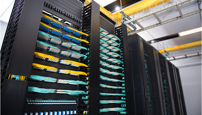
Cables are in the right position. Patch panels are terminated. All slack cables are put orderly in the cable manager. Let’s see what is missing? Well, where should the patch panels and cable managers be? Just lying on the ground? If indeed, the previous efforts for cable management is wasted. Just with a cabinet or a server rack, you can solve the problem. There are thousands of cabinet for different use, but here we refer to the network patch panel cabinet.
Network Patch Panel Cabinets Introduction
We have wall mount cabinets that has the maximum height of 12U and the normal cabinets standing on the ground that can reach to 45U. Unlike the open frame rack which consists of two or four mounting rails (called posts) without sides or doors, the wall mount cabinet is enclosed by SPCC cold roll steel panels and a glass front door to make its inside visible. The side panels can be removed easily for quick access to equipment and cabling. On the top of the patch panel cabinet, there is a cooling vent to ensure smooth airflow, preventing over-heat in it to further protect equipment. It is designed to house the 19-inch standard that is consistent with most patch panels in FS.COM or non-standard network equipment as well as network accessories. The wall mount cabinet is shipped fully assembled and is ready to mount to the wall.
As for the floor-standing network patch panel cabinet, the ventilation can be naturally achieved as the front door is perforated and the top panel is attached with brush guards to prevent over-heating. It has four casters helping with its move. Top, bottom and back cable access openings provide convenient and multiple cable routing choices to and from the patch panel cabinet.
Layout Inside the Patch Panel Cabinet
We all know that all patch panel are put in the cabinet, be it fiber optic patch panel or Ethernet patch panel. However, the question is whether it is on the front side or back and with the jacks facing in or out?
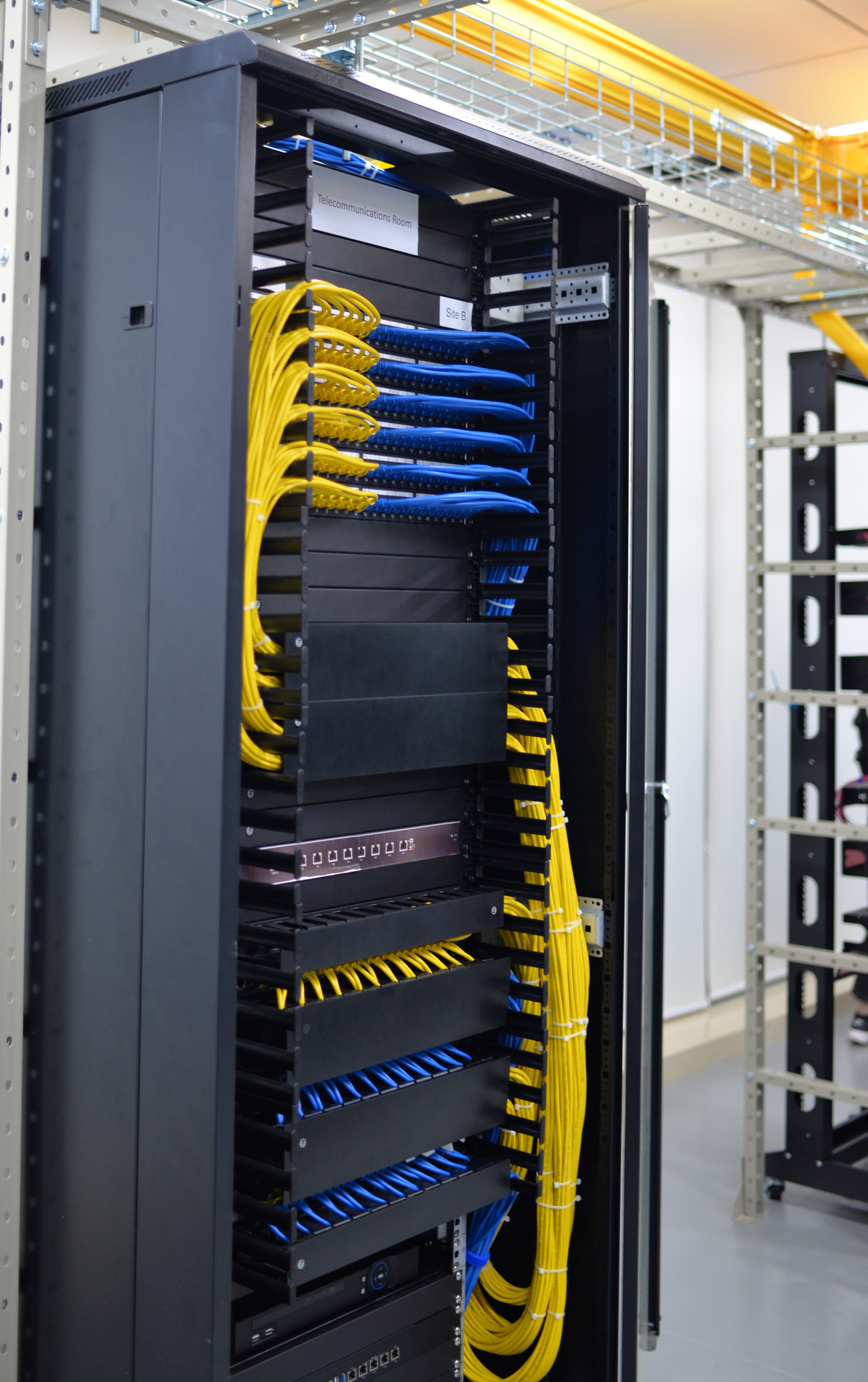
In most cases, we will start with an empty patch panel cabinet, and then install the devices on its front rails from top to the bottle. First comes the cable manager 1, then follows the patch panel 1, cable manager 2, switch 1, cable manager 3 and switch 2, with all the connectors on the back side of the patch panel cabinet. All gadgets ready, we can go on with the cabling. The patch panel here can be fiber or copper patch panel.
The importance of a patch panel cabinet is no less than that of a tiny screw or a nail. And great attention should be focused on it since the patch panel cabinet can support the other device and prevent them from external damages. A solid and durable patch panel cabinet is necessary, which is actually what FS.COM aims at. There are 9U and 12U, two choices for you to meet different application. To ensure the best performance, 1 bag of nuts and bolts, 1 T-Shaped Lever will be offered for free. And there are so many surprises in the patch panel cabinet that I want to leave it for you to find yourselves. You will find them when installing and using the patch panel cabinet from FS.COM.
Have troubles in vertical or horizontal cable management in your data center? Confused at the cables’ destinations and start points? With slack cables hanging here and there in server rack, blocking and pathway? Well, all these issues brought by point-to-point cabling will become the thing of the past as the structured cabling comes into being.
What Is Structured Cabling?
Before the 1990s, data and cabling system were proprietary which means they were vendor specified, each vendor had his own cabling system design and it was hard to have products from different vendors to work together. In the mid 1980s, the EIA was asked to develop a specification that would encourage structured standardized cabling. In 1991 the TIA published the first version of the commercial building telecommunications cabling standard, better known as TIA/EIA-568.
In the United States, we follow TIA/EIA-568-C as the structured cabling standard. It covers subsystems of structured cabling, installation methods and practices, connector and pin assignments, media types and performance specifications for horizontal and backbone cabling, connecting hardware performance specifications, recommended topology and distances, and the definition of cable elements (horizontal cable, cross-connects, telecommunication outlets, etc.)
How to Design Your Own Structured Cabling Solution
Presume that we have an empty building of four storeys, we need to design a structured cabling solution for different uses in it. One solution we must apply, also one of the subsystems of structured cabling, is horizontal cabling which can not be skipped in each floors. Horizontal cabling is the cabling that extends from horizontal cross-connect or main cross-connect to the work area and terminate in telecommunications outlets. Horizontal cabling includes the following: 1.Cable from the patch panel to the work area; 2.Telecommunications outlets; 3.Cable terminations ; 4.Cross-connections(where permitted); 5.A maximum of one transition point; 6.Cross-connects in telecommunications rooms or enclosures.
Furthermore, to achieve the connection between different floors, we need the backbone cabling, also known as vertical cabling. We can adopt it to to connect entrance facilities, equipment rooms, and telecommunications rooms and enclosures. Backbone cabling consists of not only the cables that connect the telecommunications rooms, equipment rooms, and building entrances, but also the cross-connect cables, mechanical terminations, or patch cords used for backbone-to-backbone cross-connection.
The work area is where the horizontal cable terminates and wall outlets also called the telecommunications outlet. In the work area, the users and the telecommunications equipment connect to the structured cabling infrastructure. The work area begins as a telecommunications area and includes components such patch cables, modular cords, fiber jumpers, station equipment such as computers, telephones, fax machines and so on.
The telecommunications rooms and telecommunications enclosures are the location within the building where cabling components such as cross-connects and patch panels are located. These rooms are where the horizontal structured cabling starts from. The telecommunications room and enclosure may also contain networking equipment such as hubs, switches, routers, etc.
The equipment rooms is a centralized space specified to house more sophisticated equipment than the entrance facility or the telecommunications rooms. Most often, telephone equipment or data networking such as routers, switches, and hubs are located there. Backbone cabling is specified to terminate in the equipment room.
The entrance facility specifies the point in the building where cabling connects with outside world. All external cabling such as campus backbone, inter-building, and telecommunications provider should enter the building and terminate in a single point.
Digital data is growing faster than any other commodity and its importance to businesses of all types cannot be underestimated. To learn how you can use structured cabling to better manage your data center, contact the experts at FS.COM.
Long before the born of cable manager, the mess cable management with cables hanging here and there has been a cloud over the data center and server room. How can you realize each smooth and convenient operation on your network application with network cables looking like messy spaghetti? Here we list four common cable managers to simplify your cabling and minimize the trouble during operation.
Different Types of Cable Manager
The following cable managers which you may have heard of or seen before are the most popular types in the market. Each has its unique design and characteristics.
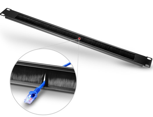
Cable Manager with Brush Strip
The panel is designed to be mounted on any 19in EIA style rack or cabinet and features built-in brush that allows passage of up to 25 cables while blocking airflow, ensuring optimal thermal performance. The steel construction provides durability, resists corrosion, and keeps your rack looking smooth and professional.
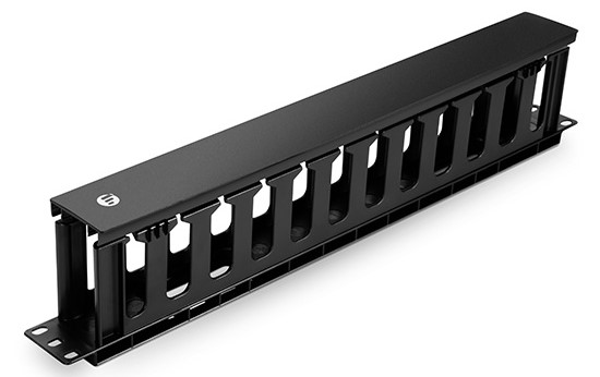
Cable Manager with Finger Duct
The FS.COM finger duct horizontal cable manager is designed with flexible fingers, rear pass-through holes and a removable cover. The soft and durable finger ducts offer proper bend radius and flexible operation of cable management, keeping the structured cabling system unhurt and totally functional.
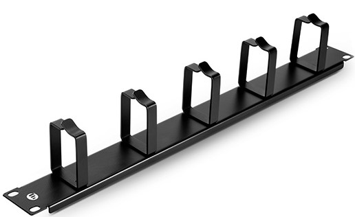
Cable Manager with D-rings
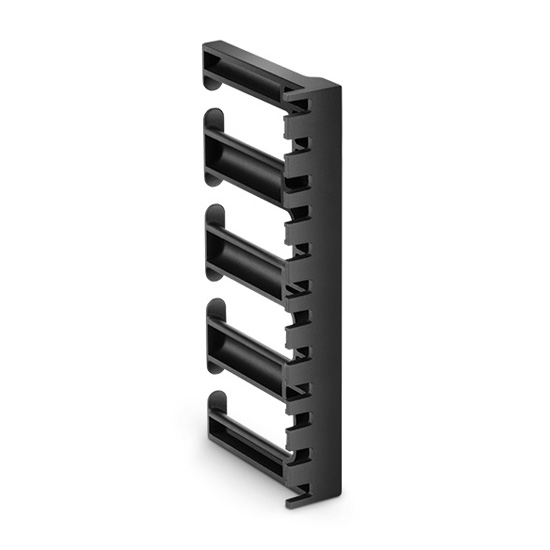
The name of D-rings cable manager originates from the fact that five metal D-rings stand vertically on the cable management panel in a good order. Horizontal cable management panels with D Rings are built with steel for strength and durability. Easily route large amounts of cable through robust rings. The D-Rings organize patch cords and maintain a required bend radius. They are available in sizes of 1U and 2U.
Cable Manager with Bend Radius Finger
This cable manager is equipped with six or five bend radius control fingers, consuming much fewer material. The total length of it is 222mm. Light in weight, this type of bracket can be installed in specific areas of the rack, rather than along its entire height. Moreover, it can be stacked to reach any height(U), so it can be an alternative of higher vertical cable management.
How to Apply Cable Manager
Cable managers often come together with patch panel to make the patch cables in the front side of patch panel more orderly. Generally, in a server rack, the cable can’t either be put solely on cable manager since it is incompetent for termination, or be applied to just a patch panel due to its imperfect cable management. Therefore, to realize the perfect cable management, we need to deploy this couple at the same time. The cables going out from the patch panel have already gone through the management process, but it should go to the next cable manager installed above or below the patch panel, so that the whole cable management can be finished. Additionally, some people will need the further step to bring the cables that are from horizontal cable management to the vertical cable managers standing at the both sides of the cabinet.
Conclusion
Never look down upon cable management, otherwise the cables haphazardly thrown around will be your nightmare. In case it damages the wires and cause other hazards, now it’s time to arrange your cables properly. FS.COM has many kinds of cable managers to help make your life neater!
Not so long ago, fiber optic communication came into people’s life and provided us with great convenience. Its advantages could be found in such aspects as long transmission distance, large capacity and fast transmission speed. Therefore, the demand of fiber optic products like fiber optic transceiver, fiber optic patch panel and fiber optic enclosures has been soaring these years. But the products on the market are miscellaneous. Today, we will have a closer look at the two major fiber optic enclosure manufactures, namely Panduit and FS.COM. Panduit fiber optic enclosure and FS.COM fiber optic enclosure, which will you choose?
Comparisons of Fiber Optic Enclosures in Panduit and FS.COM
Panduit is a global manufacturer of physical infrastructure equipment that support power, communications, computing, control, and security systems. FS.COM (Fiberstore) is a leading global high performance end-to-end cabling and connectivity solutions provider which provides a complete portfolio of products and solutions.
Focusing on three groups including rack mount fiber enclosure, wall mount fiber enclosure and enclosure accessory(fiber optic cassette for example) which are all applied in 1U cable managemet, I have summarized several critical items that are most concerned by customers in the following table.
Rack Mount Fiber Enclosure
Items
FS.COM
Panduit
Products
FHD-1UFCE Fiber Enclosure
FCE1U Enclosure
Fiber Count
≤96 Fibers
≤96 Fibers
Type
Rack Mountable
Rack Mountable
Price
≈89$
≈289$
Wall Mount Fiber Enclosure
Items
FS.COM
Panduit
Products
FHD-FWME2 Fiber Optic Wall Mount Enclosure
FWME2 Enclosure
Fiber Count
≤48 Fibers
Unknown
Type
Wall Mountable
Wall Mountable
Price
≈60$
≈116$
Fiber Optic Cassette—Enclosure Accessory
Items
FS.COM
Panduit
Products
MTP-12 Ultra High Density MPO/MTP Cassette
FC26N-12-10AS
Fiber Count
12 Fibers
12 Fibers
Dimension (HxWxD)
11.3x92x171.2mm
35 x 89 x 125mm
Price
≈72$
≈293.4$
Panduit Fiber Optic Enclosure or FS.COM Fiber Optic Enclosure
Seen from the clear data and information about 2 pairs of fiber optic enclosures form FS.COM and Panduit, we can distinguish that there is a large gap between the product price and fiber count. The price, a significant factor that influence purchase, is greatly different from each manufactures. Fiber count of the roughly same products are also different, with FS.COM products outnumbering Panduit ones.
And the enclosure accessories provided by FS.COM cater to various needs. They have different fiber counts, connector types, and adapter types, and minimum insertion and return loss.
Price, and fiber count, the top three considerations of purchasers when looking for the ideal products, have been analyzed in the type of table and text for your reference.
Conclusion
When it comes to the choice between Panduit fiber optic enclosure and FS.COM fiber optic enclosure, you should figure out your own requirements to determine which to buy. The renowned Panduit and FS.COM both have their own reasons for each progress and designing. At FS.COM, we offer lifetime warranty and limited warranty for different products varying on the materials, workmanship, usage rate, and the availability of the spare parts for each product. And the relatively reasonable price is also the reason why so many people choose FS.COM. As a company born and grew in China, FS.COM grows with and by people. And it returns people with high quality and best service.
All above are some of my personal opinions and conclusions. The thinking and words just represent my own idea, if you find out any unreasonable, please forgive me and your ideas will be appreciated.
The patch panel, a significant element in cabling design, has many ports on it. Through these ports, the cables are located elsewhere in your building. Patch panel at present has fiber and copper patch panel(also known as Ethernet patch panel), two choices for us. As we all know, a single fiber optic patch panel is not available to all kinds of fiber cables. The same is to copper patch panels which are classified as Cat5e patch panel, Cat6 patch panel and so on.
CAT5e Ethernet Patch Panel VS. CAT6 Ethernet Patch Panel
Both as the copper patch panel, Cat5e patch panel and Cat6 patch panel don’t have many differences, except that Cat5e patch panel usually works with Cat5e, while Cat6 patch panel can work with both the corresponding Cat6 cable and any earlier generation of Cat cable. The patch panels themselves don’t have many practical differences. However, there is indeed a difference in the wire gauge specified between Cat5e and Cat6. The cat6 wire is thicker in that Cat6 usually has 23 AWG copper conductors compared to only 24 AWG in Cat5e cable.
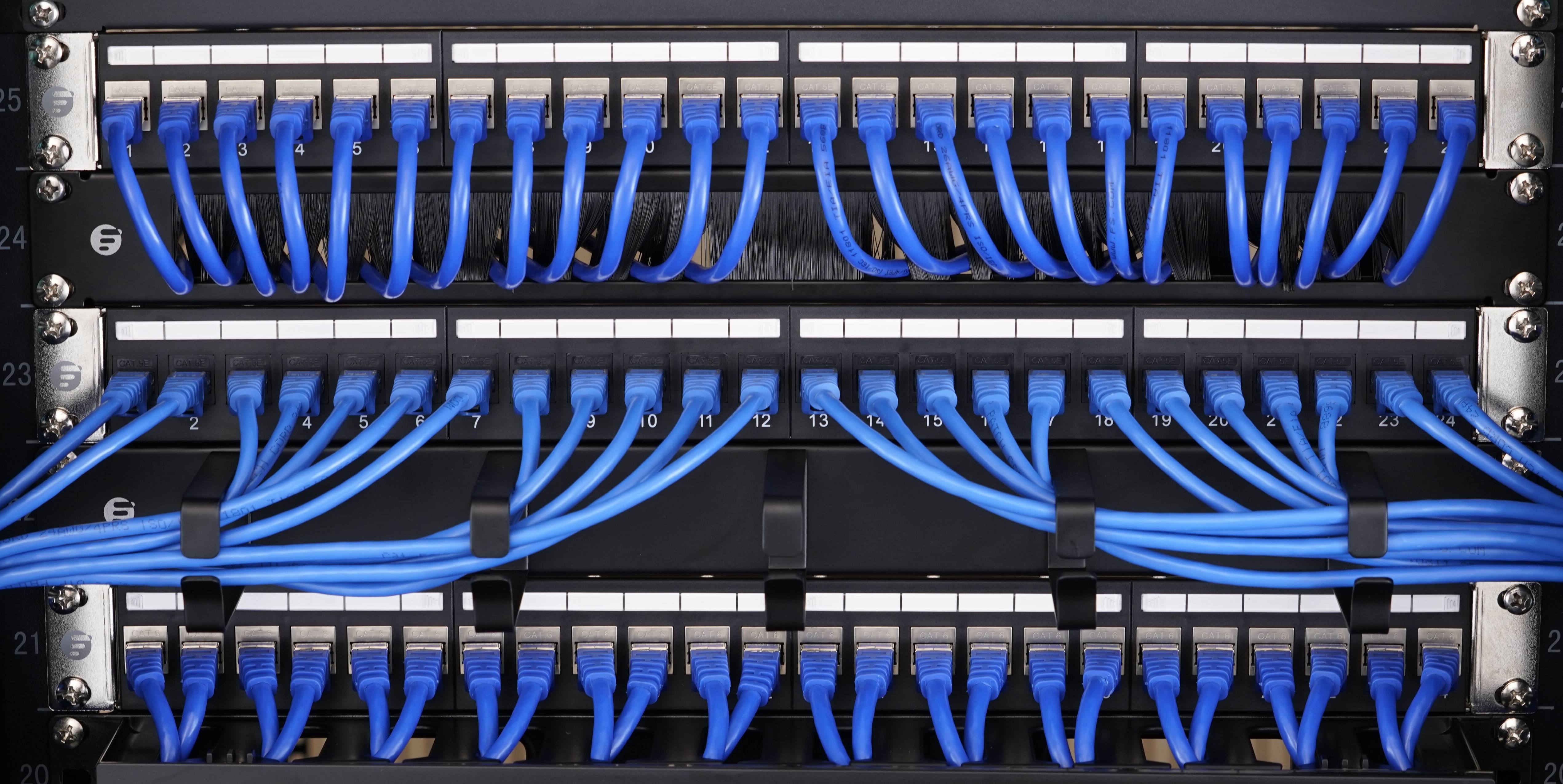
The 24 port patch panel used for different cables are both welcomed by customers. 24 port cat6 patch panel offered by FS.COM acquires acknowledgments from many customers and IT experts. With easy installation and top-quality performance, the high quality patch panel is designed for Fast Ethernet applications. 24-port Cat5e patch panel is the most popular in the market, which has punch down and feed-through patch panel for customer choice. And when applying patch panels to special environments, for example nearby motors, generators, air conditioners, and even office mainstays such as fluorescent lights and printers, you should carefully consider between shielded and unshielded patch panels.
Shielded Ethernet Patch Panel VS. Unshieleded Ethernet Patch Panel
Shielded and unshielded patch panels are required to match with the shielded and unshielded copper cable applications. Shielded patch panels are designed for high EMI (Electro Magnetic Interference) environments. If the application environments have special requirements for crosstalk and EMI functions, especially when the copper cable runs near power cables then you should choose to use shielded Ethernet cables with shielded patch panels. However, someone may wonder whether they can use unshielded patch panel for shielded cable. To be honest, it depends on the environment in which your cable will run through. If the place has no high power electrical wires, you can go with unshielded patch panel. On the flip side, if you are in a noisy environment like using arc welders or near high power radio transmitters, then you’d better select the shielded one. FS.COM shielded and unshielded patch panels can meet not only 1G network speed, but also 10G network.
For both shielded and unshielded applications, you can find what you need at FS.COM. The port number marked on the FS.COM patch panel provides easy cable identification. The cable manager on the rear side is removable, providing efficient and organized cabling.
Conclusion
CAT5e and CAT6 cables are the most popular Ethernet cables on the market. To create a nicely organized cabling environment, choosing the right patch panel is essential. Sometimes Cat5e, Cat6 or other Ethernet cables need to be managed in a single panel, in this type of situation, the blank keystone patch panels can support mixed cabling with installation of different rj45 insert modules. In addition, you can customize your patch panel according to your specific applications. FS.COM provides a large variety of patch panels and Ethernet cable and also presents a selection of cable managers to help you create your ideal cabling network. For more details, please visit our website.
As one of the important tools in horizontal cable management and the assist of fiber panel, the horizontal cable manager has been warmly welcomed by the public since its debut. The horizontal cable manager comes in varied types such as brush strip cable manager, finger duct cable manager. And the height of it may vary as the network system demands. The fantastic design horizontal cable manager with finger duct is what we will talk about today.
Horizontal Cable Manager with Finger Duct Overview
The FS.COM finger duct horizontal cable manager is designed with flexible fingers, rear pass-through holes and a removable cover. It can be mounted to standard 19 and server rack and cabinet providing well-organized cabling quickly and easily. 1U and 2U versions are both available at FS.COM. Unique hinge cover allows for easy cable moves,adds and changes to connections, saving time and money. The soft and durable finger ducts offer proper bend radius and flexible operation of cable management. 2U version increases more space for Ethernet cable runs.The two holes on the main plate allow for front-to-back or back-to-front cable runs. The finger ducts can be used for both upside and downside cable management. Simplify network maintenance and cost, as well as support future growth and cabling demands.
How the Finger Duct Horizontal Cable Manager Works?
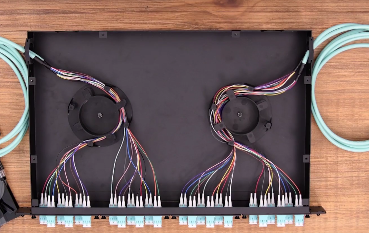
Take 1U finger duct horizontal cable manager as an example, it can be mounted above or below the fiber optic patch panel, with the hinge cover side facing towards us. Open the cover and 12 gaps between 11 finger ducts. The cable is inserted into the above patch panel, and then 2 cables share a same gap. The left 6 couples of cables are all combed to the left vertical cable manager, and the right 6 to the right horizontal cable manager. The two holes on the back of the cable manager are designed for the cables inserted to the below patch panel. The procedure is all the same with the front cabling.With all the cables in their position, you can load the cover.
Vertical and Horizontal Cable Manager
Vertical cable manager is standing vertically on both sides of the cabinet, while the horizontal one is mounted in the cabinet. In addition, whatever the height of the cabinet is, the vertical cable manager can satisfy your needs by mounted with each other. You can choose them according to your actual needs. However, the combination of them shown in the video is no doubt the optimum option. The more detailed information of the two cable managers:Horizontal and Vertical Cable Management At a Glance
This cable manager with finger duct is an optimum option for your horizontal cable management. Get it to protect your equipment, improve the appearance and accessibility of your rack. I am sure you will be content on its hassle-free compatibility with your rack. Any question or puzzle is expected to be asked immediately. With your recommendations, we can go further and grow faster. And also, we sincerely hope that with our products and service, you can gain in both work and life.
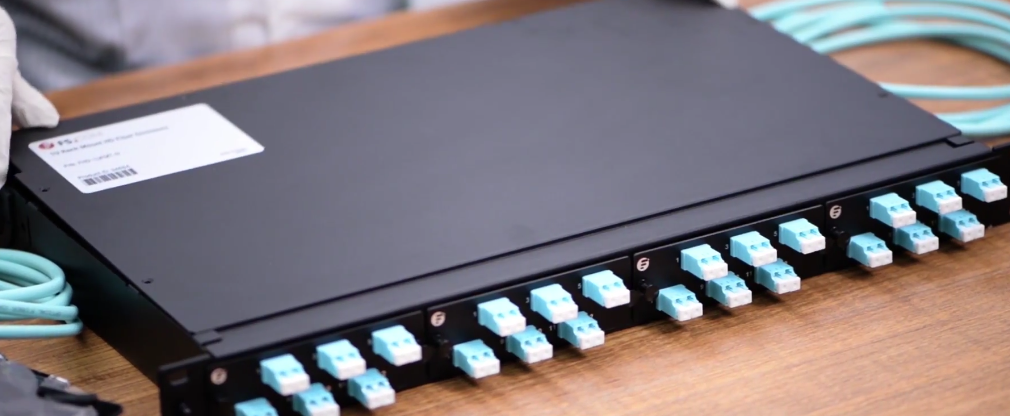
Patch panel is defined as the interface between multiple optical fibers and optical equipment. It’s a termination unit that helps networking and fiber distribution from wiring closet to various terminal equipment. Fiber optic patch panel is a mounted hardware unit containing an assembly of port locations in a communication or other electronic or electrical system. Fiber optic patch panel is used to terminate the fiber optic cable and provide access to the cable’s individual fibers for cross connection. They are mostly mounted in 19 inch relay racks, but they can also be mounted on freestanding rails, in cabinets and also on walls.
Fiber Optic Patch Panel Types
Fiber optic atch panel are divided into two types based on different designs, the wall mount and rack mount category. Both types can house, organize, and protect fiber optic cable and connectors. Rack mount patch panels come in flat and angled versions while the wall mount patch panel is used for direct termination of several fibers, and are mostly equipped with routing guides to limit the bend radius for enhanced strain-relief control. They can also be classified according to the count of ports. The common patch panels are come in 12 ports, 24 ports, 48 ports and 96 ports. The height of it can also vary as 1U, 2U, 3U and so on. For more about the types, click here.
How to Connect Fiber Optic Cable To Fiber Patch Panel
Insert the adapters into the mounting plate, then fix the mounting plate in position. Prepare cables based on standard termination procedures and ensure there is enough surplus cable to work with. Connect the cable by fixing the gland and roll the excess fiber onto the spool. After that, remove the protection cap and insert into position in the adapter. Once the cables are all attached, it’s better to use a zip tie to secure the cables in a bundle. In a typical setup, the connection consists of a shorter cable plugged into the front side of the patch panel and a longer cable plugged into the back. In this way, the panel can take the place of otherwise expensive switching equipment. This is the extract from How to Connect Fiber Optic Cable to Fiber Optic Patch Panel. You can find more useful information in it.
How To Use A Fiber Optic Patch Panel
Getting a fiber optic patch panel is mainly for two reasons: termination and better cable management. As for patch panel termination, it is the step to terminate fibers on the patch panel, a precise task required much attention. As for cable management, here I recommend you to accompany it with cable managers. From a top-down perspective, the order of the devices in a cabinet should be: fiber patch panel 1, cable manager 1, fiber patch panel 2, cable manager 2 For fiber optic cabling cable management, you should plan the location of your fiber connectivity hardware carefully, including fiber patch panels. You can choose between direct cross connection and patch panel. It is also necessary to arrange your routing and dressing of your fiber patch cords if you choose to use fiber panels. In the meantime, you also have a choice to use fiber cable management brackets to avoid the dangling fiber patch cables. Owning a fiber optic path will not only spare you a lot of time and energy in cabling design, but also present you a neat cabling system, which will bring you efficient work.
It seems that we have already known that the fiber patch panel is the bridge of fiber patch cables. Fiber patch panel, also known as fiber distribution panel, serves as a convenient place to terminate all the fiber optic cable running from different rooms into the wiring closet and provides connection access to the cable’s individual fibers. Fiber patch panels are termination units, which are designed with a secure, organized chamber for housing connectors and splice units.
How Does Patch Panel Termination Units Works?
We know that there are two major termination solutions for fiber cable: field terminated and pre-terminated. The pre-termination, with most devices terminated by the manufacturers in advance, requires less efforts when installing than field termination does. Therefore, this post is going to offer a glimpse into the field termination which describes the termination of the fiber optic cable in the field or the termination after installation.
Fiber Patch Panel Termination Procedure
In the termination process, the fiber optic cable need to be pulled between two points, then connectors will need to be attached and then connected to a patch panel. In addition, before they can be attached to a panel, connectors need to be attached to each individual strand, and a variety of tools will be needed. With field termination, we can determine the cable length accordingly, and fiber optic bulk cable is very easily to pull from either end of the installation circuit. To carry out the termination, such tools are needed as fiber optic enclosure, fiber cable, patch panel, cable ties, connector panels, permanent marker, fiber optic stripper, cleaver, metric ruler and rubbing alcohol.
To terminate the cable, first slide the boot onto the fiber. Strip the fiber to at least about an inch and a half . Place a mark at 15.5 mm for ST and SC connectors or at 11.5 mm for LC connectors. Clean the stripped fiber with an alcohol wipe and remove any debris. Set the stripped fiber into the cleave and cleave it. Insert the cleaved fiber into the rear of the connector until the mark align with the back of the connector body. Slight the boot up and over the rear of the connector body. After the termination, transmission testing of assemblies need to be performed.
In the final fiber patch panel termination, first, open the front and rear door of the patch panel, and remove the covers. Remover the inter stain relief bracket. Second, use cable ties to put the cables on the bracket. The fibers should be put inside the clips on the tray to segregate the fibers from A and B slots. Put the patch panel into the panels clips. Take the excess fiber slack into the slack management clips. Make a bend in the fiber to maintain slight pressure on the connection.
Conclusion
The processes in the device connection and cable management are linking with each other that missing any or failure in any one will result in the imperfect system, or even the damage. If we own a fiber patch panel, we should make full use of its termination function. The products provided by FS,COM enable you to perfect your cabling system.
When the fiber patch panel is loaded with cables, your cabling is almost finished with the core elements all ready. You can achieve fast and smooth Ethernet connectivity. But turning around, you may find a mess caused and left by the installation. The slack cables without careful comb are hung casually, resulting in a sloppy look just like the noddles being stirred. If we have a look at an expert, it is common to find that they all manage their cables in a good order. And today, we will reveal the secret of the marvelous layout — horizontal and vertical cable management.
Horizontal and Vertical Cable Management
When you try to simulate others’ cabling system, you will inevitably find that the cable management comes in two varieties, horizontal and vertical. When installing cables in a fiber enclosure, you will undoubtedly have to run them both vertically and horizontally. The best solution for this cabling is to run all the cables horizontally from the server directly to the vertical cable management rack. With these two solutions, you can gain many benefits like enhanced availability through reduced downtime, and improved system performance through reduced crosstalk and interference. We all know that crosstalk is harmful and will damage more or less the data transmission. What’s more, it enables us easier and safer access to individual components so as to achieve improved maintenance and serviceability. And the moves, adds and changes will be simplified.
Horizontal and Vertical Cable Manager
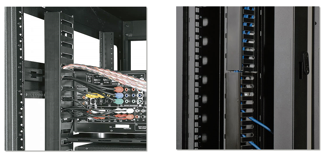
With horizontal cable managers, the cables from equipment in racks can be routed neatly and properly and away from damage. If you are using flat-faced patch panels or network switches form which cables come above or below, horizontal cable manager will complete the support pathway for patch cords between the cabling section and the exact connection point (port) on the patch panel or switch. Alternately, horizontal management can be used to create rack-to-rack pathways for patch cords. The FS.COM finger duct horizontal cable manager is designed with flexible fingers, rear pass-through holes and a removable cover. It can be mounted to standard 19 and server racks and cabinets providing well-organized cabling quickly and easily. 1U and 2U versions are both available at FS.COM.
Vertical cable manager just as seen in the below image, utilizes the additional space at the both sides of the cabinet to manage the slack from patch cords, and make sure that they can easily route the largest cable diameter in your plan. For static environments, you can consider installing another vertical cable manager behind the racks, which does not block access to components in the space between the racks. Vertical racks can be also installed under a desk or against a wall and accommodate networking equipment up to 4 RU. Its dual sided fingers enable both front and back well-organized cabling.
Conclusion
With horizontal and/or vertical cable managers, the human errors which may be committed previously due to the confusion of a mess of cables can be easily prevented in horizontal and vertical cable management. Once you have to deal with fiber and copper cables at the same time, apart from our multimedia modular panel, FS.COM cable managers can be used to house and organize fiber and copper cabling while keeping separation between the two.
Some people say that patch panel is a waste, and only a network switch matters. Others, however, hold firmly that patch panel is a significant gadget without which you can hardly imagine how the network cabling will look like. As far as I am concerned, we should view it accordingly.
Why We Should Use Patch Panel?
Apart from the easier cable management it provides, its function resembles the railroad switch. And let’s compare the cables to rails to see how it works. With a railroad switch(patch panel), the train(data) can travel from A to B, C and even more destinations, otherwise it can only go from A to B, or C to D. This article, What Is a Patch Panel Used for?, has explained it thoroughly. In addition, FS.COM offers extensive selection of patch panels.
How to Connect Patch Panel to Switch?
Having made clear of the function of patch panel and the switch, let’s see together how do they connect in the network cabling in case of mistakes in the layout process. Assume that we have a two 24 port feed through patch panels and two 24 port switch, and all the devices mentioned below. We don’t take the punch down panel here is because it has to be punched down first then to connect the cabling system. If you use a punch down patch panel, the methods and procedures to punch down it have been listed in my previous article—How to Punch Down Cat6 into Patch Panel.
Step 1
Find a cabinet large enough to accommodate both the patch panel and switch. And mount the 24 port patch panels and switches all in the same rack. The order from the top to the bottom is like this, patch panel 1, spacer, switch 1, patch panel 2, spacer and switch 2.And prepare the cables in a proper length.
Step 2
Prepare the cable in a proper length to avoid the mess.
Step 3
Use the top 12 ports on the patch panel for the bottom 12 ports on the switch, and the bottom 12 on the patch panel for the top 12 ports on the switch. The one set of patch cables would be just a bit shorter than the other 12.
Step 4
Connect the modulars on the rear side of the patch panel with the cables that go to each unit or room.
OK, congratulation. Now you have a very neat and beautiful cabling system. When powering on, the whole system will work orderly in their own places.
Conclusion
All in all, a patch panel is more of an extension of your Ethernet cables. It's used for the purpose of neatness and the achievement of data crossover. A switch connects your devices into a network allowing them to communicate and share files with each other. To help you better understand the ways to connect the two, we are planning to produce a video to illustrate the steps in details. You can refer to FS.COM for more information and follow us for the further knowledge.